The Timers (alongside of the Counters, of the Coils and Relays and of the Sequence Commands) are one of the principals components in PLC, acting as chronometers in the system, measuring the time of occurrence of the events associated to the control.
There are, in the LCE, four types of timers, that are mapped, respectively, to the instructions IL TON, TONR, TOF and TOFR: (Obs.: this TOFR is not implemented in the STEP 7)
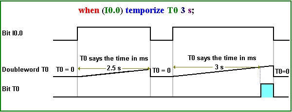
1. Temporize (cond):
when (cond) temporize T0 3 s;
In the example above, the doubleword variable T0 (temporizing variable) says, in ms, the time (that can come into instruction in ms - milliseconds, s - seconds, min - minutes or h - hours) past since from instant that the condition cond was true by the last time (or since that the flow of power reached the instruction by first time after that the control entered on the run mode, if cond already began true). If cond is false, doubleword T0 remains 0 (off or false). If cond was true and changes to false, doubleword T0 changes to 0, turning off/reseting the bit variable (0/1 - on/off) associated to T0.
When T0 reaches the value of the preset time, the second parameter (3 s, in the example above), the bit variable associated to T0 will be turn on (or set in 1 - true), but the doubleword T0 will continue saying the time, as nothing had occurred. When cond change to false, the bit variable T0 will change to its state original off (or reseted to 0 - false) and doubleword T0 will be put in nought, remaining frozen in zero, no saying the time until cond changes to true.
Functioning Diagram
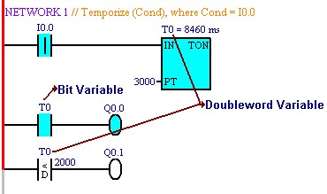
Obs.: the way that we use the variable T0 will define if we deal with doubleword variable (comparisons, assignments or mathematical operations) or bit variable (bit-logic operations), as exemplified into diagram below:
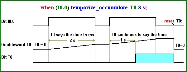
2. temporize_accumulate (cond):
when (cond) temporize_accumulate T0 3 s;
It works like the anterior, with the difference that when cond changes to false after the bit variable T0 has gone to on, this T0 will not change to its original state off and the doubleword T0 will not be set in zero, keeping the value of the time past until this moment and resuming the temporization from this value when cond change to true again. That is, it accumulates the time that cond is true.
To return the bit variable T0 to its original state off and the doubleword variable T0 to zero, we must put in the control a command reset or turn_off with parameter T0 (reset T0; or turn_off T0;).
Functioning Diagram
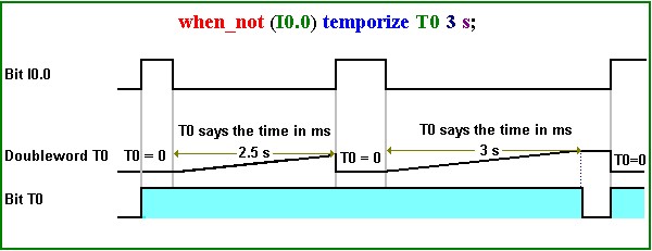
3. Temporize (not cond):
when_not (cond) temporize T0 3 s;
In the command above, when cond changes from false to true the bit variable associated to T0 will be turned on. The doubleword variable T0 says the time past since the last instant that the condition cond have changed from true to false. If cond changes again to true, T0 come backs to zero, but the bit variable associated to T0 will continue on.
When doubleword T0 reaches the value of the preset time, the second parameter (10 s, in the example above), the bit variable associated to T0 is turned off and the time said in T0 will remain frozen, but when cond changes from false to true the bit variable T0 will return to the state on and the doubleword variable T0 will be reset to zero.
Functioning Diagram
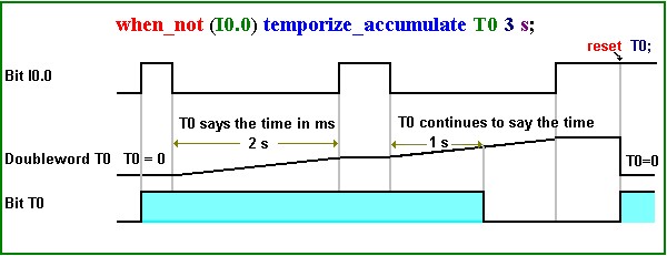
4. Temporize_Accumulate (not cond):
when_not (I0.0) temporize_accumulate T0 3 s;
It functions like the anterior, with the difference that when cond changes to true after the bit variable T0 has gone to off, this T0 will not change to on and the doubleword variable T0 will not be set in zero, saying the value of the frozen time past until this moment and resuming the temporization from this value when cond changes to false again. That is, it accumulates the time that cond is false.
To the bit variable T0 changes to on, we must put in the program a command reset or turn_off with parameter T0 (turn_off T0; or reset T0;), to change the timer to the state initial with doubleword T0 in zero and, then, when cond change from false to true, the bit variable associated to T0 will be on.
Functioning Diagram
Obs. 1: the response to change of the inputs can delay up to one scan cycle, although such wait was not represented at the diagrams above.
Obs. 2: the temporizing variable must have, necessarily, the form Tn, where n can vary from 0 to 511.