In the SimuPLC 4.1.0, there are 64 bit input variables (Input - I), named from I0.0 to I7.7, and 64 bit output variables (Output - Q), named from Q0.0 to Q7.7. (Obs.: it's used Q, instead of O, the abbreviation of output, to avoid the confusion that, of other mode, fatally would happen between the zero value - 0 - and the O of output.)
The bit variables from I0.0 to I0.7 are grouped in the byte variable IB0. At suchlike form, the bit variables from I1.0 to I1.7, I2.0 to I2.7, ..., and I7.0 to I7.7 are grouped in the byte variables IB1, IB2, ..., IB7, respectively.
At same manner, the bit variables from I0.0 to I1.7 are grouped in the word variable IW0, and the variables from I2.0 to I3.7, I4.0 to I5.7 and I6.0 to I7.7 are grouped in the word variables IW1, IW2 and IW3, respectively.
Finally, the bit variables from I0.0 the I3.7 are grouped in the doubleword variable ID0, and the variables from I4.0 the I7.7 are grouped into doubleword variable ID1.
At similar manner, the variables QB0, QB1, QB2, ..., QB7, QW0, QW1, QW2, QW3, QD0 and QD1 are formed of output bit variables from Q0.0 to Q7.7.
See example below, with the use of variables composed by bits:

The bit input variables on/off are represented by eight LEDs bars on the left side on the screen of the Simulator, and the output ones present the same arrangement on the right side.
When the user clicks on an input LED, the pattern behavior is that the respective input changes of state, from off to on or vice versa (alternative behavior, to open a dialog box to change its activation color, can be obtained with the command Input-LEDs Colors of the Edition menu). Other form to turn on and turn off the correspondent input is, simply, to click on design of the correspondent switch from ladder diagram, that represents any instruction load, and, ald, or or old of the implemented control.
On the other hand, when the user left-clicks on a output LED, always is open a dialog box permitting that is changed its activation color.
When the user positions the mouse pointer, during one second, on a LED or on any field on bars of analogical variables, if such variable was associated to a significative name, this one will be presented, as exemplified below:
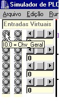
Obs.: we can change the state of the respective input, from off to on and vice versa, left-clicking on the respective LED, or left-clicking on the image of the contact on the design of the ladder diagram, if such contact is relative to this input, naturally.
See click in comparison contacts.
See right-click on ladder diagram.