In the SimuPLC 4.1.0, there are 32 analogical input variables (Analogical Input Word - AIW), named from AIW0 to AIW31, and 32 analogical output variables (Analogical Output Word - AQW), named from AQW0 to AQW31.
Represented in vertical bar of variables on the left side on the screen of the Simulator, above of every AIW there is a scroll bar which, when it's clicked on the right or the left arrow, the value of the respective word variable is increased or decreased by 100 units, respectively; and when it's clicked on the proper scroll bar's body, on the right or left of the positional mark, this value is increased or decreased by 1000 units, respectively.
The AIW variables are showed either from AIW0 to AIW15 or from AIW16 to AIW31. To alternate the visibility form between a group and the other, press Ctrl+W.
The AQW variables are showed in vertical bar on the right side of the screen, presenting the current values correspondent to the current program on running.
With rigor, these inputs and outputs named analogical are not really analogical, they are only 16-bit digital variables (word format) that approximate the behavior of real analogical variables.
The physical quantities in general, the electrical tension and current, time, temperature, pressure, illumination, force, weight, velocity, acceleration, distance, angle, sounding intensity, volume, resistance, mass, etc., are analogical, in the sense whic they can assume any real value within a possible interval, in opposite to the digital variables, that can assume only a finite number of values within considered interval.
Digital electronic circuits does not get work directly with analogical quantities, which can be processed directly only with analogical electronics, in general based in operational amplifiers. For that digital circuits can handle analogical input signals, these ones must previously be transformed in digital variables, in a process known as sampling, that consists in to approximate, with the lesser possible error, a signal digital to an analogical one, sampling it in small intervals of time and converting the values of the samples in digital values (conversion A/D or AtoD).
In this manner, in PLC equipments we deal with analogical signals indirectly, translating it in digital approximated form with conversion A/D, and assigning the results to the variables here named analogical.
In the output of the signals, when the destination requires analogical format, the system must convert the digital signal to analogical one, with D/A converter (DAC).
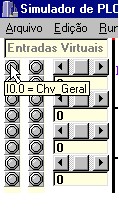
When the mouse pointer stays during one second stopped on a LED within bar of virtual bit variables or on any field in the bar of virtual analogical variables, if such variable was associated to a meaningful name, this will be presented:
Obs.: we can change the value of the respective analogical input left-clicking on the scroll bar above of the edition field of the variable, or on the drawing of the comparison contact on ladder diagram, if such contact is relative to this analogical input, naturally. Clicking in the superior part of the design of the contact, the respective analogical input is increased in 1000 or 100 units, if the pointer is positioned, at moment of the click, little above or too much above of the middle point of the contact image, respectively; and will be decreased in 1000 or 100 units if the click happens in the inferior part of the design, at similar form.
See click on relays' contacts.